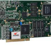
Echtzeit Linearisierung
G0A-4020-0
Echtzeit Linearisierung
Characteristic scaling
Characteristic scaling
The characteristic curve scaling is used to scale the recorded signals in real time on the measurement card. The scaling takes place directly on the signal processor of the measurement card and therefore does not require any computing power on the PC side. The characteristic curve scaling on the measurement cards of the Multichoice PCI and USB series is only available with the “Online linearization” option enabled. The characteristic curve scaling is set in the measuring program via settings of the analog acquisition block. This transfers a list of the support points to the DSP, which describe the signal scaling. The scaling takes place on the entire set voltage range. The definition of the support points takes place in a separate text file in which the corner points are simply stored line by line.
To enable scaling, (2 exp. X) +1 corner points are required, whereby 0 If fewer coefficients are selected than are available in the file, the following values are ignored.
The coefficient files can be created very comfortably, for example with Excel, and saved as a text file. The point “.” Is used as the decimal separator. used!
An example of a coefficient file:
0.0
1.0
5.0
6th
10
The number of points given is 5 ((2 exp. 2) +1)
In the example, when the input voltage range is set from -10 to +10, the recorded measured values are scaled as follows according to the definition of the output range:

-10 to -5V -> 0 to 1V
-5 to 0V -> 1 to 5V
0 to 5V -> 5 to 6V
5 to 10V -> 6 to 10V
Online PWM and FM
Frequency modulation and 24-bit pulse width modulation available
Implementation in hardware
Since October 2001, new digital output types have been available for the cards of the Multichoice PCI series. The previously available pulse-width modulated output has been completely revised, earlier dropouts when writing a new pulse-pause ratio are a thing of the past. The PWM and FM switching mimics are implemented in the FPGA of the measurement card, so that this module takes over the controls in hardware, so to speak. This solution enables higher update speeds and better stability of the output without taking up computing time of the signal processor.
Completely new possibilities
With some drivers, pulse width modulation and frequency modulation are even available at the same time, so that pulse width and frequency can be modified in parallel in a circuit diagram during runtime. This parallel modification enables completely new solutions for previous problems such as valve controls or test stands.
Better resolution In
addition, a second variant of the pulse-width modulated output was developed which, instead of the previous 16-bit depth with a clock rate of 500 kHz, has a depth of 24 bits and a clock rate of 10 MHz. This significantly increased the accuracy of the PWM output. Furthermore, the frequency spectrum now ranges from 0.6 Hz to 5 MHz.
Frequency modulation as a free bonus
The third innovation was frequency modulation. This behaves like a pulse-width-modulated output with a variable frequency and a specified mark-to-space ratio.
The PWM modulates the pulse width of a square wave signal with a constant period. The pulse width is given as a percentage of the period. If the pulse width is 0%, the PWM output is always low. If it is 100%, the output is always high. At 50%, the low and high levels are the same length.
Pulse width signal with a) 0%, b) 25%, c) 50%, d) 75% and e) 100%
Frequency modulation (FM)
With FM, the period of a square wave signal is modulated. The duty cycle remains constant. The smallest possible period is the maximum possible frequency and the largest possible period is the minimum possible frequency.
Analog triggers
Analog triggers
Triggers are conditions that are monitored during the runtime of a measurement. These conditions relate to the measured values that have just been recorded; in the case of individual value processing, this monitoring takes place within a specified response time depending on the sampling rate.
Up to 10,000 times faster than software
triggers on the PC If trigger conditions are implemented by measuring programs on the PC system, the response times to a trigger that has occurred are well beyond the millisecond range, since the measured value is first recorded, transferred to the PC system, processed and the control commands sent back to the measurement hardware and output there. However, if this trigger is executed on the signal processor, it is processed immediately after the measurement value has been recorded before it is transmitted to the PC. The reactions can be started directly on the measurement card without the PC having to control it separately. The response times are in the nanosecond range without the PC system being burdened with additional controls.
Flexible combinations possible
By using triggers during a measurement, it is possible to react to events during a measurement at short notice. The limit or threshold values to be monitored are set before the start of the measurement and can be changed dynamically during the actual measurement. Several trigger conditions can be selected per channel, which can also be linked to one another using Boolean logic.
Control of external events
A trigger event that has occurred can start or stop a measurement, digital outputs can be configured or an analog output is controlled. Optionally, these trigger conditions can also activate or deactivate each other so that a whole network of dynamic triggers is available depending on the course of the measurement. The trigger conditions can be defined in a retriggerable manner, i.e. either deactivate or reactivate after a condition has been fulfilled in order to carry out the same or a changed monitoring.
Versatile trigger types Limit
or threshold value monitoring for edges, limit values or window conditions are available as trigger conditions; the measured values can be offset against the previous values and acted on depending on the slope of the resulting curve (gradient slope), this also within threshold value and window conditions.
Easy to automate
The adjustable actions, which are automatically carried out when an event is fulfilled, allows control or monitoring to be implemented within a guaranteed response time. For example, test bench monitoring with emergency shutdown via the digital outputs is conceivable, which shuts down the test bench quickly and safely if one of the monitored measured variables is exceeded, without external intervention being necessary. Saving the triggered trigger event with the last value is possible without any problems so that the cause of the emergency shutdown is not lost.
Easiest operation
Depending on the measuring program used, the trigger parameters are set simply via the user interface of the card settings. The predefined masks ensure user-friendly and simple operation, so that even complex conditions can be easily configured. Here you will find examples for trigger configurations in DIAdem , DasyLab and LabView .
Echtzeit Onlinefunktionen
Echtzeit Onlinefunktionen der Multichoice-IV PCI/USB-Serie
Die Messkarten der MultiChoice-IV Serie sind in der Lage, dank dem auf den Messkarten vorhandenen Signalprozessor, die erfassten Messwerte in echtzeit wehrend der Erfassung nachzubearbeiten.
Wenn eine Weiterverarbeitung von Messwerten während der Datenerfassung erforderlich ist, können diese Funktionen durch die hohe Eigenintelligenz der Messkarten auf die Hardware ausgelagert werden. Dieses entlastet das messende PC-System deutlich. Weiterhin werden die Verarbeitungen der Messwerte in Echtzeit durchgeführt, da jeder Messwert direkt nach der Erfassung die Verarbeitung durchläuft, bevor er weitergereicht wird. Die Latenzzeiten zwischen einem eingetretenen Ereignis und der folgenden Reaktion liegen durch den Einsatz des Signalprozessors im Mikrosekundenbereich. Eine solch schnelle Steuerung, Regelung und Reaktion ist ohne Eigenintelligenz auf der Messkarte niemals realisierbar. Da die Karten der MC4PCI-Serie mit bis zu zwei eigenen Prozessoren ausgerüstet sind, bietet diese sehr hohe Eigenintelligenz eine Vielzahl an Möglichkeiten.
Die MultiChoice-IV (PCI/USB) Karten bieten mit den verfügbaren Treibern eine Reihe der der folgenden Fünktionen. Dabei können alle Onlinefunktionen beliebig kaskadiert werden,
so das z.B. eine Triggerung der gefilterte Messdaten möglich ist oder eine Filterung nach dem Berechnen einer FFT.
| Analoge Trigger | Triggerfunktionen bieten eine Überwachung der Messwerte auf konfigurierbare Schwellen. Bei Erfüllen einer Triggerbedingung können Messungen gestartet oder gestoppt werden darüber hinaus können digitale Ausgänge gesetzt werden, um externe Ereignisse auszulösen. Die Trigger der Multichoice PCI-Serie sind in der Lage, auf eintretende Ereignisse in Echtzeit zu reagieren. |
| Filter (FIR und IIR) | Filter dienen zur Reduktionen unerwünschter Störanteile in einem Nutzsignal. Die Filter entfernen bestimmte Frequenzanteile des Gesamtsignals und sind so in der Lage, das Ergebnis der Messung zu verbessern. Die Filter können frei eingestellt werden, da die Berechnung der erforderlichen Koeffizienten dynamisch erfolgt, eine Einschränkung auf bestimmte Standardfilter ist nicht vorhanden. |
| FFT | Die FFT wandelt das analoge Signal von der Zeitebene in die Frequenzebene. Es ist kein kontinuierliches Signal mehr sichtbar, sondern die einzelnen Sinusschwinungen mit Amplitude und Frequenz, aus denen sich das Zeitsignal zusammensetzt. |
| Online-PWM und -FM | Wenn über analoge Messwerte, z.B. von einem Durchflussmessgerät, phasenan- oder abschnittsgesteuerte Aktoren steuern sollen, so muss eine Skalierung zwischen analogen Messwerten und der zugehörigen Pulsweiten- oder Frequenzmodulation erfolgen. Diese Skalierung sowie sofortige Ausgabe der neuen Werte kann direkt auf der Messkarte erfolgen. Dazu werden minimal und maximale Pulsweite bzw. Frequenz sowie der zugehörige analoge Messwertbereich angegeben. Die Skalierung erfolgt linear und äquidistant. |
| Kennlinienskalierung | Die Kennlinienskalierung ermöglicht eine Skalierung und Projektion der reellen analogen Messwerte auf beliebige Funktionen. Die Kennlinie wird durch eine flexible Anzahl an äquidistanten Stützstellen definiert, zwischen denen anhand der analogen Messwerte linear skaliert wird. Durch die Festlegung der Reihenfolge kann auch auf die skalierten Messwerte gefiltert oder getriggert werden. Durch Skalierung der Messwerte auf dem Signalprozessor kann im Anschluss auf die skalierten Messwerte getriggert, gefiltert bzw. sonstige Onlinefunktionen angewendet werden, ohne das das PC-System belastet wird. |
Grundlagen digitale Signalverarbeitung und online FFT auf einem Signalprozessor
Grundlagen digitale Signalverarbeitung und online FFT auf einem Signalprozessor
Hier finden Sie weitere Informationen zu den verfügbaren Onlinefunktionen.
![]() Grundlagen zum Thema digitale Filterfunktionen
Grundlagen zum Thema digitale Filterfunktionen
![]() FFT – Fast Furier Transformation
FFT – Fast Furier Transformation

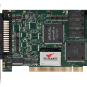
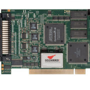
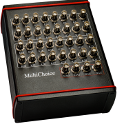

 Goldammer GmbH